nvidia-smi issues? Get NVIDIA CUDA working with GRID/ Tesla GPUs
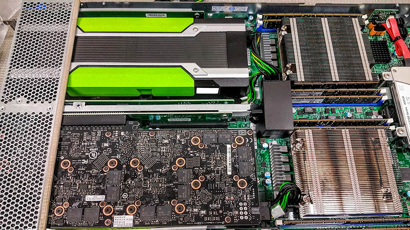
Supermicro SuperBlade GPU with dual NVIDIA GRID cards
When it comes to server and professional workstation graphics, NVIDIA makes some monster GPUs. As one might expect, strange things can happen when you start using these larger memory footprint GPUs such as the NVIDIA GRID K1, K2, M4, M6, M60 and Tesla K10, K20, K20x, K4, K80, Tesla M40 and etc. We had to make some significant BIOS changes to be able to use these cards with Ubuntu 14.04 LTS. Here is how we managed to fit 8 GPUs per blade server which would allow up to 80 GPUs in a 7U rack (10x 8GPU systems.)
The Symptom
We recently added a dozen NVIDIA GRID M40 cards each with 4x GM107L GPUs and 4GB of GDDR5 each for a total of 16GB of onboard memory. We wanted to have the ability to test machine learning algorithms on multi-GPU setups while still using very little power. These are special cards that we obtained but assume they are similar to the NVIDIA GRID K1 however with Maxwell instead of Kepler architecture, lower power, and less GRID driver support for Citrix, VMware and Microsoft VDI applications. You likely will need to be a special NVIDIA customer to be able to get these GPUs as there is very little information online about them.
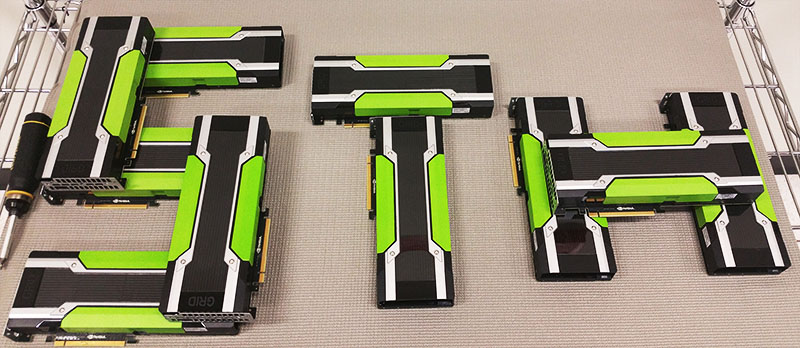
NVIDIA GRID M40 STH
The Supermicro SuperBlade GPU blades allowed us to add two cards for 8x GPUs in each blade. The GPU SuperBlade chassis supports 10 blades so one can fit a total of 20 GPUs and 20 CPUs across 10 systems. With support for the newest Broadwell-EP processors, each chassis can handle 20 GPU and 440 cores/ 880 threads (using 2x Broadwell-EP Xeon E5-2699 V4 processors.)

Supermicro SuperBlade GPU x2 and MicroBlade
With NVIDIA’s quad GPU cards like we are using (and the K1), one can actually test algorithms with 8 GPUs per system in a very low power envelope (e.g. our blades are running at under 500W even with dual E5-2698 V4 chips and the 8x GPUs running at 98% utilization.)
Supermicro SuperBlade GPU with dual NVIDIA GRID cards
If you install a card into a system running an out of the box Ubuntu 14.04 LTS installation (or other distributions even 16.04 LTS from what we have seen with dailies), you will likely install the card and then try running nvidia-smi, a tool for monitoring the cards. Upon running nvidia-smi you are likely to get a hang in the terminal window you are using:

NVIDIA nvidia-smi hang – not working
Another symptom we saw was a PCI Resource Error in the BIOS. Luckily, the PCI Resource Error and nvidia-smi issue we were able to fix with a few BIOS tweaks.

NVIDIA GRID M40 PCI Resource Error in BIOS
Also, applications like CUDA and NVIDIA cuDNN will not work which can be frustrating if you are using Tensorflow, Theano, Caffee or another machine learning setup. We have a guide on how to fix this.
Supermicro BIOS Changes for GRID/ Tesla
Since we were using various Supermicro GPU SuperBlade server nodes for our testing, we are showing BIOS changes for this. From what we understand, some server vendors have similar options that are less obvious. For example, HPE servers may have a hidden menu that you can hit Ctrl-a into to get to the relevant menu to change 64-bit PCI support. The Supermicro GPU SuperBlades we are using have these menu options easily visible, but you do need to know how to set them.
The first screen we want to access is: Advanced->PCIe/PCI/PnP configuration
There are three key settings you want to set:
- Above 4G Decoding = Enabled (should be default)
- MMIOH Base = 256G
- MMIO High Size = 128G
Here is what the screen should look like when you are done if you have a single 4 GPU card:

NVIDIA GRID M40 GPU – BIOS settings for 16GB GPU
These setting are important to get the setup working.
Moving to two cards and a toal of 8 GPUs here are the settings we used:
- Above 4G Decoding = Enabled (should be default)
- MMIOH Base = 512G
- MMIO High Size = 256G
Here is what these settings looked like with two 4 GPU cards for a total of 8 GPUs in each Supermicro GPU SuperBlade:

NVIDIA GRID M40 GPU – BIOS settings for 2x 16GB GPU EFI
The big change here was the MMIOHBase and MMIO High Size changes to 512G and 256G respectively from 256GB and 128GB. Once we had those updated, the other step was fully diving into UEFI. Everything we tried with Legacy boot mode on Supermicro and a few other servers just refused to accept this many GPUs.
You will also note in the pictures above we changed the onboard Video OPROM to EFI. We did this so we could turn off CSM mode.

NVIDIA GRID M40 GPU – BIOS CSM settings for 16GB GPU EFI
We also had to change from dual (Legacy and UEFI) mode to pure UEFI. Our advice here is to transition to UEFI across the board.

NVIDIA GRID Boot Mode UEFI
We have seen some vendors struggle supporting 8x GPUs in a single system but the above settings will even get the dense blades to operate with this high number of GPUs. Installation of two GPUs in the Supermicro SuperBlade GPU nodes requires removing about 12 screws. After we did the first blade, our subsequent GPU blade updates took in the 5-7 minute range using a manual screwdriver. We were able to change BIOS settings before or after installation which is nice since one 8x PCIe x16 slot system we tested from another vendor would not POST and get into BIOS with the cards installed (requiring a return trip to the data center.) We would suggest ensuring you can boot before leaving the data center but with the SuperBlade GPU nodes this was not an issue.
From here you can boot into Ubuntu 14.04 LTS as normal. If you are using NVIDIA GPUs with Tensorflow, as an example, you can download the NVIDIA CUDA 7.0. deb and run:
As a hint here, in most settings we have found sudo to be important. Here is the nvidia-smi output with our 8x NVIDIA GPUs in the Supermicro SuperBlade GPU node:

Success nvidia-smi 8x GPU in Supermicro SuperBlade GPU node
If you are still having issues, we have had a few machines where we needed to make a file called /etc/udev/rules.d/90-modprobe.rules (use sudo nano to make it) and add:
We could then run:
And everything worked for us after we made that update.
Final thoughts
When it comes to building machine learning systems, most of the big GPU compute shops we have seen are using 8x big GPU nodes. These machines can take upwards of 2.6kW each and cost a ton to setup. The two cards with 4 GPUs each solution was excellent as it allows us to simulate an algorithm on eight GPUs in a single system before scaling it up. Likewise, in the blade chassis we can have a single 7U box with networking built-in, that can simulate a small scale 80 GPU cluster (or 20/40 GPUs in officially supported configurations.) While scaling up to larger GPUs would certainly be (much) better we have seen this architecture work at clients that are looking for lower cost alternatives to buying large new machine. Setting this all up was far from easy, but luckily with multiple blades at our disposal our rate of trial and error was awesome. You should, of course, consult your system manufacturer, however this will hopefully help folks on their path of troubleshooting nvidia-smi issues.
More information and where to get cards we used
You can find more information about these cards on STH in a number of places:
- Our NVIDIA GRID M40 introductory piece (coming soon)
These are very hard cards to get. The easiest place right now is on ebay. Here is a GRID M40 ebay search.
The list of UEFI feature(Workload Optimized 2)
UEFI settings of Workload optimized 2 is as follows. In addition, customers can not change the following settings.
Boot Feature
Setting items (key)
Value set as (Default)
Instead of the startup the logo display screen, it is set to display the POST screen.
In order to support an OS other than UEFI-compatible OS, it is the corresponding set to the traditional BIOS using the CSM.
Set the display mode of the option ROM. Force BIOS is selected to use the Option ROM display mode that has been set by the system BIOS.
Set the power-up state of the NUMLOCK key.
If an error occurs, and then force the system to select [Enable] to wait until the key <F1> is pressed.
In the setting to perform the notification of the interrupt signal, it is set to take effect if the option ROM is installed on more than one expansion card.
After a failed initial boot, it is set to be able to re-boot the system from the boot device.
This setting is to enable the watchdog timer to restart the system.
The system will control how to shut down when the power button is pressed.
This setting is for the power state at the time of recovery after a power failure. Currently it is set to be able to resume the last of the power state before power loss.
CPU Configuration
Setting items (key)
Value set as (Default)
It is the monitoring settings of BIOS to reduce the level of electromagnetic interference.
It is the support setting for the Intel Hyper-Threading technology to improve the performance of the CPU.
Valid setting of the CPU core. In the default setting, it is set “0” in order to enable all of the CPU cores in the system.
It is the setting for the processor that can specify the area and non-area capable of running the application code in memory.
Setting the inventory number (PPIN) control of the protected processor in the system.
It is a setting for read-ahead data and instructions flow from the main memory to the L2 cache and to improve the performance of the CPU.
This setting is for prefetching 128 bytes of cache line as the CPU configuration.
It is a prefetcher setting of the DCU streamer. It prefetches the data stream from the cache memory for the access data and processing the DCU(Data Cache Unit) to speed in order to improve the performance of the CPU.
In order to improve the performance of the network connection and the system, it is a setting for IP prefetcher in the DCU (data cache unit) to prefetch the IP address.
In order to improve the efficiency of the transfer and data access, it is a setting for the Intel DCA (direct cache access) technology.
Based on Intel‘s hyper — threading architecture, each logical processor (thread) is assigned an ID (sensor assistance) of 256 APIC with an 8 — bit bandwidth. The APIC ID extends from 8 bits to 16 bits to provide 512 sensor assistance for each thread to improve CPU performance.
Based on the Intel VT-d, to enable or disable the X2APIC_OPT_OUT Flag on the system.
It is a setting to ensure the security of data utilizing Intel’s AES (Advanced Encryption Standard).
It is a setting in order to use support of Intel Virtualization Technology for support of direct I/O VT-d by reporting I/O device assignment (virtual machine monitor) to VMM via DMAR ACPI table.
Setting items (key)
Value set as (Default)
It is a setting to support the power-saving mode. Customize the power settings of the system is selected as a default setting.
Configure the settings of the power performance bias adjustment by the BIOS or OS.
It s a setting for the control method or how actively is used the particular hardware-based power management options.
Configure the settings of the power-management features.
Setting items (key)
Value set as (Default)
It is a setting that enables a system to adjust the voltage and core frequency of the processor to take advantage of EIST (Enhanced Intel SpeedStep Technology) and automatically reduce power consumption and heat dissipation.
The setting is used in turbo mode in order to enhance the system performance.
This function is to change the P-state Coordination (power-performance state) adjustment type. P — state Coordination is known as SpeedStep for Intel processors. “HW_ALL” to change the P-state Coordination type of the hardware component is selected.
Setting items (key)
Value set as (Default)
This setting is to limit the C-state package registration.
It is a setting for the BIOS to enable the report of the CPU C3 state (ACPI C2) to the OS.
It is a setting for the BIOS to enable the report of the CPU C6 state (ACPI C3) to the OS.
Setting items (key)
Value set as (Default)
it is a setting to carry out the reduction of CPU power consumption, in order to reduce the clock cycle and voltage of the CPU when it’s in a significantly stopped state.
Chipset Configuration
Setting items (key)
Value set as (Default)
It is a setting to always be cleared during the electrical tuning EV_DFX Lock bits that are disposed on the processor.
This item is only displayed.
Setting items (key)
Value set as (Default)
It is a setting to support the Intel I/OAT (I/O Acceleration Technology).
It is a setting that does not support the snoop mode for each CB equipment.
It is possible to violate the strict ordering rules on the PCI bus for transactions when a particular transaction is completed before other transactions that have already been enqueued. It is a setting to enable support for Relaxed Ordering.
Setting items (key)
Value set as (Default)
It is an Intel virtualization technology setting. It performs Direct I/O VT-d support by reporting I/O device assignment to VMM (virtual machine monitor) via DMAR ACPI table.
It is a setting to enable the access control service.
It is a setting to enable the interrupt remapping in order to improve the performance of the system.
Setting items (key)
Value set as (Default)
It is a setting to choose the frequency for the QPI link connection.
It is a setting to support the Link L0p in order to reduce the power consumption.
It is a setting to support the Link L1 in order to reduce the power consumption.
It is a setting to enable the Cluster-On-Die support, in order to improve the system performance in cloud computing,
It is a setting is to enable the Early Snoop in order to improve the system performance.
Run the Directory mode, to enable the in memory snoop directory.
It is a setting to enable the Isochronous support in order to meet the QoS requirements (Quality of Service).
Setting items (key)
Value set as (Default)
It is a setting for applying the POR restrictions on the DDR4 frequency and voltage programming.
It is a setting for the maximum memory frequency of on-board memory module.
It is a setting to enhance the integrity of the system performance and data.
It is a setting to set the base line of the power limit at the time of execution of the DRAM module.
it is a setting to set via the automatic voltage control during an idle state of the CPU, thereby reducing power consumption, in order to improve the reliability of PU.
The 4G address space or more memory that is divided between the 2 sockets is set to be enabled.
It is a setting to support the A7 (addressing) mode in order to improve the memory performance.
Setting items (key)
Value set as (Default)
It is a setting to enable the RAS support.
It is a setting to enable support for memory sparing for rank, in order to improve the memory performance.
It is a setting that allows to enable / disable the rank sparing mode.
Patrol scrub is the process that allows the CPU to correct the correctable memory error detected in the memory module and send the correction to the requester (the original source). If this item is enabled, the IO hub is read and if there is no delay due to internal processing, write back 16 K cycles per cache line. With this method, approximately 64 gigabytes of memory behind the IO hub is scrubbed daily.
In this feature, it sets the waiting time of the system before the next patrol scrub is executed.
Demand scrub is a process that enables the CPU to correct correctable memory errors detected in memory modules. If the CPU or I/O issues a demand read command and it is found that the data read from the memory have a correctable error, it corrects the error and sends it to the requester (original source). The memory is updated as well.
It is a setting to support a device tagging.
Setting items (key)
Value set as (Default)
It is a setting to support the legacy USB devices on board.
It is a work-around solution setting for the OS that does not support the XHCI handoff.
It is for operating systems that do not support EHCI handoff. If this item is enabled, EHCI ownership change will be requested by the EHCI driver. Settings are enabled and disabled.
Provides full legacy USB keyboard support for operating systems that do not support legacy USB devices. This setting enables I / O port 60h / 64h emulation support.
It is a setting to enable the USB 3.0 support.
It is a setting to enable the EHCI (Enhanced Host Controller Interface) support of the USB 2.0 connector.
It is a setting to enable the EHCI (Enhanced Host Controller Interface) support of the USB 2.0 connector.
Mmio high size что это
Reddit and its partners use cookies and similar technologies to provide you with a better experience.
By accepting all cookies, you agree to our use of cookies to deliver and maintain our services and site, improve the quality of Reddit, personalize Reddit content and advertising, and measure the effectiveness of advertising.
By rejecting non-essential cookies, Reddit may still use certain cookies to ensure the proper functionality of our platform.
For more information, please see our Cookie Notice and our Privacy Policy .
Get the Reddit app
Welcome to r/gaminglaptops, the hub for gaming laptop enthusiasts. Discover discussions, news, reviews, and advice on finding the perfect gaming laptop. Join our passionate community to stay informed and connected with the latest trends and technologies in the gaming laptop world.
What are the differences between the two? Throttlestop shows these two modes, my BIOS shows the 200/200, and HWINFO shows 90/135. Am using an MSI GS66, 12700H. Also, do higher power levels = generally more performance like in GPU TGP? Thanks!
Что даст это изменение в BIOS, North Bridge Configuration
«По умолчанию адресации памяти оптимизирован для 64-битных операционных систем, в результате чего объем доступной памяти для 32-разрядных операционных системах с Low MMIO Align вы можете настроить его для оптимизации настроек для 32-битной операционной системы.
Для 64-разрядных операционных он должен быть установлен 1024″
ASRock Поддержка
Видимо опция, помогающая x86 системе увидеть лишние десятки-сотни мб ОЗУ, если установлено 4 и более гб ОЗУ.
«By default memory addressing is optimized for 64 Bit operating systems, resulting in less available memory for a 32 Bit operating system, with Low MMIO Align you can set it for optimized settings for a 32 Bit operating system.
For a 64 bit operating it should be set to 1024
ASRock Support»